
 français
 русский
 español
 العربية
Search
What Are You Looking For?
Search

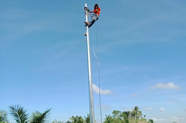
Definition: Hot-dip galvanized steel structures engineered for medium-voltage distribution lines, transformer mounting, and rural/urban power networks.
| Parameter | Specification | Standard/Grade |
|---|---|---|
| Voltage Class | 4.6kV / 11kV / 22kV / 33kV | IEC 60038 |
| Height Range | 9–18m | Modular sections |
| Material | ASTM A572 Gr.50 / S355JR | Yield: 345-355 MPa |
| Coating | Hot-Dip Galvanizing (HDG) | Min. 610g/m² (ISO 1461) |
| Top Diameter | 100-180mm | Taper: 1.2%/m |
| Base Diameter | 220-450mm | |
| Wind Resistance | 160 km/h (IEC 60826 Class 4) | 12.5mm radial ice load |
| Bending Moment | 20-150 kN·m | At GL (ground line) |
Tapered Monopole: Conical design for optimal load distribution
Joint Types:
Flange-bolted (M24 bolts, 8.8 grade)
Slip-fit with shear pins (for rapid assembly)
Standard Heights:
graph LR
33kV --> 15m/18m
22kV --> 12m/15m
11kV --> 9m/12m
| Component | Specification |
|---|---|
| Crossarms | Hot-dip galvanized steel (1.5-3m length) |
| Insulator Pins | 16-24mm Ø, spaced per phase clearance |
| Phase Spacing | 11kV: 0.9m / 33kV: 1.8m (IEC 61936) |
| Ground Clearance | ≥5.5m for 33kV (AS/NZS 7000) |
Direct Burial:
Depth = 10% pole height + 0.6m
Backfill: 95% compacted granular soil
Concrete Caisson:
1.2m Ø × 2.5m deep (for soft soils)
Rebar cage: 6×T16 verticals with T10 ties
| Component | Function | Standard |
|---|---|---|
| Neutral Conductor | Top-mounted (ABC systems) / Crossarm-mounted | IEC 60502-2 |
| Grounding | 50mm² Cu cable to 2×3m rods (≤10Ω) | IEEE 80 |
| Surge Arresters | Polymer-housed (30kA, 36kV MCOV) | IEC 60099-4 |
| Warning Signs | "DANGER 33kV" at 2.5m height | ISO 3864 |
| Feature | Steel (33kV) | Concrete (33kV) | Wood (33kV) |
|---|---|---|---|
| Lifespan | 50+ years | 40 years | 20 years |
| Failure Mode | Bend deformation | Brittle fracture | Rot at base |
| Ice Load Capacity | 25mm radial | 20mm radial | 15mm radial |
| Maintenance | Zero | Crack inspection | Pest control |
| Recyclability | 100% | Limited | Low |
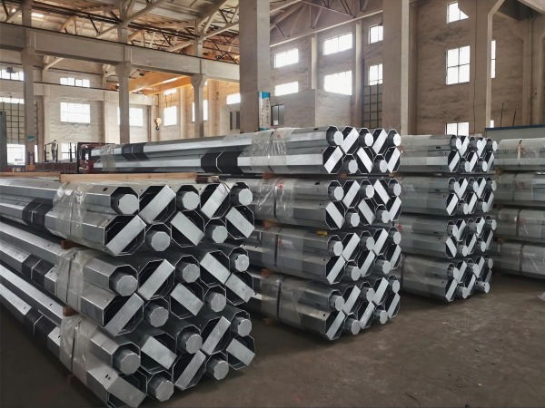
HDG Process:
Acid pickling (HCl, 10-15%)
Fluxing (ZnNH₄Cl₂)
450°C zinc bath immersion (6-10 min)
Coating Thickness:
Base: 85μm
Weld zones: 70μm (minimum)
Sacrificial Anodes: Optional for coastal/industrial zones
Height: 12m
Crossarms: 2×2.4m (horizontal V-configuration)
Conductors: AAC 150mm² (3-phase + neutral)
Ground Clearance: 5.0m
Height: 18m
Crossarms: 3×3.0m (delta formation)
Conductors: ACSR 240/40mm²
Ground Clearance: 6.5m
Site Survey:
Soil resistivity testing (Wenner 4-pin method)
Overhead line scan (LiDAR clearance check)
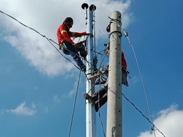
Erection:
Crane lift with spreader bars
Verticality tolerance: ≤1:500
Commissioning:
Insulator cleaning (silicone coating)
Torque check: 90% yield strength of bolts
Megger test: >500 MΩ (phase-to-ground)
| 18m 33kV Pole | Cost (USD) |
|---|---|
| Pole + Hardware | $1,800–2,500 |
| Foundation | $600–1,200 |
| Installation | $1,000–1,500 |
| Total | $3,400–5,200 |
| Note: 40% lower lifecycle cost vs. concrete over 30 years |
Project: Saudi Arabia 132/33kV Substation Feeder
Challenge: Sand abrasion + 55°C temperatures
Solution:
Extra-thick HDG (100μm) + epoxy topcoat
Concrete collars at ground line
Results:
Zero corrosion after 8 years
Withstood 90km/h shamal winds
Structural: EN 40-3-3 / ANSI O5.1
Electrical: IEC 61936 / IEEE 1127
Safety: OSHA 1910.269 (step bolts/D-rings)
Quality: ISO 9001 + ISO 3834-2 welding
Engineering Tip: For 33kV lines, specify corona rings on insulators where altitude >1000m to reduce RF noise.
For custom designs: Provide soil class, wind/ice zone, and conductor tension for pole class selection (Class 1 to Class 5 per IEC 60826).
Learn more at www.alttower.com


 IPv6 network supported